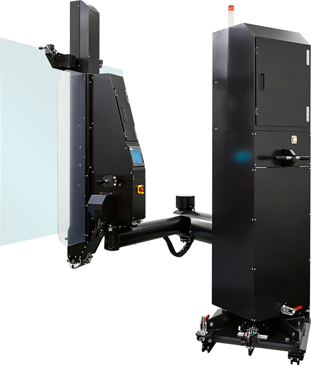
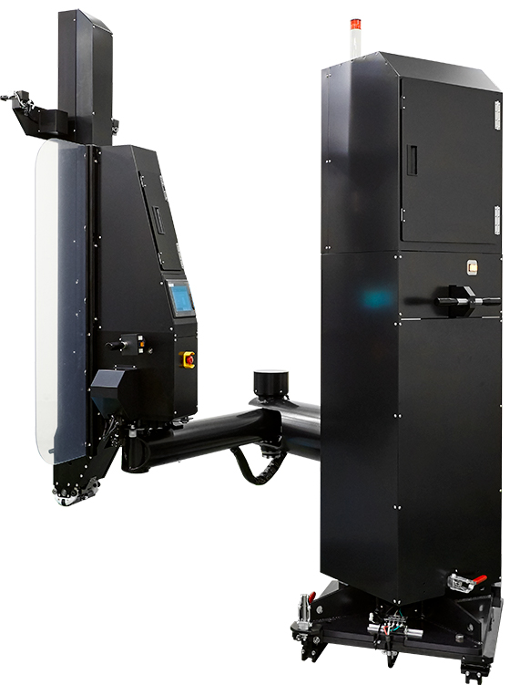
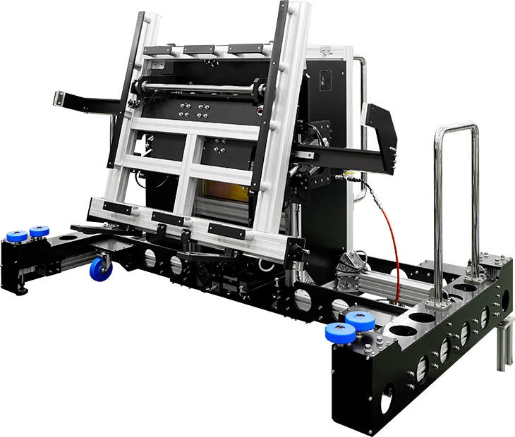
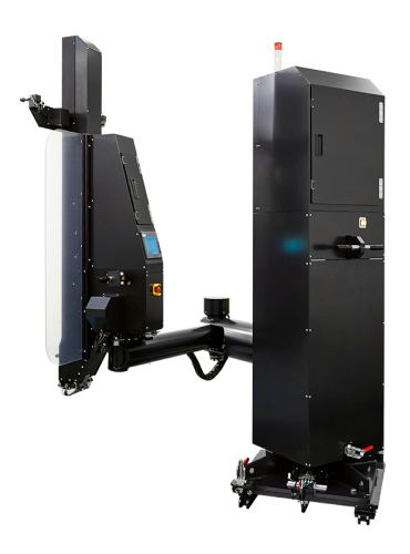
| Product Explanation | The assist arm is an assist device for safely and correctly transporting photomasks used in the production of liquid crystal and organic EL displays, which have become quite large in recent years. The operator can perform the operation following the instructions on the assist arm monitor to lessen the burden of operation. Further, in addition to the standard model, we also offer a center standard type with a larger bottom claw operation range that can be selected to match the specifications of the production equipment.
|
|---|---|
| Basic Specifications | (1) Transported mask size
X direction = 800 mm (Min.) to 1550 mm (Max.) Y direction = 500 mm (Min.) to 1500 mm (Max.) Thickness = 5 mm (Min.) to 13 mm (Max.) |
| Hand |
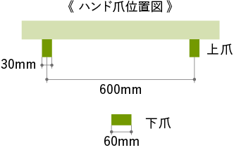
(1) Hand Shape ● One 60 mm wide mask clamp claw is placed in the center of the bottom aide of the mask and two 30 mm wide claws are placed on the right and left sides on the top of the mask. (2) Clamp/Unclamp Method (3) Top claw drive = Servo motor + Clean actuator (Ball screw) (4) Top claw vertical stroke = 1050 mm (5) Bottom claw drive = Servo motor + Ball screw (6) Bottom claw vertical stroke = 30 m (7) Mask clamp claw material (mask contact area) = Black Delrin The black Delrin mount is a side type that is held by screws.
|
| Tilt Area | (1) Comes with a touch panel for basic operations (conditions menus selection, etc.).
(2) The person operated hand employs an orientation control handle. Comes with a close at hand switch for transporting while the mask is grasped. (3) Comes with a hood to protect the equipment from the dust coming off of people. (4) Comes with an emergency stop switch. |
| Controller | (1) PLC controller (Made by Mitsubishi Electric)
(2) Equipped a rotating warning light (with a buzzer) |
| Arm | (1) The configuration is rotating part → Z-axis part → 1st arm → 2nd arm.
(2) Equipped with a weight for offsetting the arm and hand as a cylinder or electro-pneumatic regulator is not used. (3) Rotating stroke = 316° (4) Z-axis stroke = 840 mm (5) Z-axis operation method = Ball screw + Servo motor (6) The 1st arm and 2nd arm joints are equipped with an electromagnetic brake to support the push back force when tilting the mask. A switch is used to operate the brake |
| Tilt Driver | (1) Stroke = 19°
(2) Drive method = Ball screw + Servo motor |
| Rolling mechanism | (1) Stoke = Approx. ± 0.2°
(2) Drive method = Eccentric cam + Servo motor |
| Safety Measures and Debris Countermeasures | (1) The weight of the Z-axis moving part is offset by a weight. This makes possible movement with little torque.
(2) A safety bumper operates and the motor is stopped when another part is accidentally impacted when the assist arm is set in the catcher (during Z-axis operation). (3) A close at hand switch is used for all handover operations after conditions selection (transport unit, mask size, sheet thickness, material, etc.). In addition, the handover can be performed by pressing the switches in the order that they flash. (4) If a problem is discovered during device operation (check by a person), it is possible to reverse operation from that state. (5) Cleanroom measures are taken for the drive units of the upper and lower claws of the hand where a vacuum pump sucks up debris within the drive units. (6) Products for clean operation are used to grease the ball screw and LM guide and excess oil is wiped away. (7) The assist arm lock mechanism is designed not to generate debris. |
| Other functions | (1)The hand servo driver is placed at the top so as not to block the field of view. In addition, it also has a cover to prevent dust generation.
(2)The tilt operation for mask handover can only be operated while the switched is pressed and stops when the switch is released. |
PRODUCTS INFORMATION
What is photomask transport?
Photomasks are used to produce liquid crystal displays and organic EL displays. As these have become larger in recent years, they can no longer be easily transported by people and so assist arms were developed to help transport them. Using them allows large and heavy photomasks to be correctly and safely transported between the manufacturing processes where they are required.
Product Features
- Provide the accuracy required for transport to inspection and measurement equipment.
- The main areas are made more compact to allow the position to be known and checked to provide excellent operability.
- This is an assisting device, so there is no need to enclose it like a robot and it can be installed with existing equipment.
- It can also support automated transport.
- Peripheral equipment can also be built around the assist arm to create devices for packaging and shipping products.
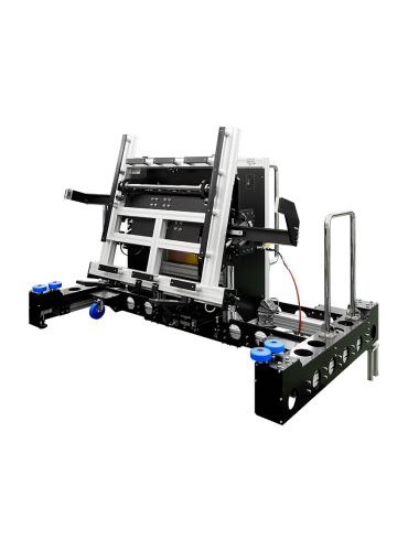
Assist arm (standard model/center standard type)
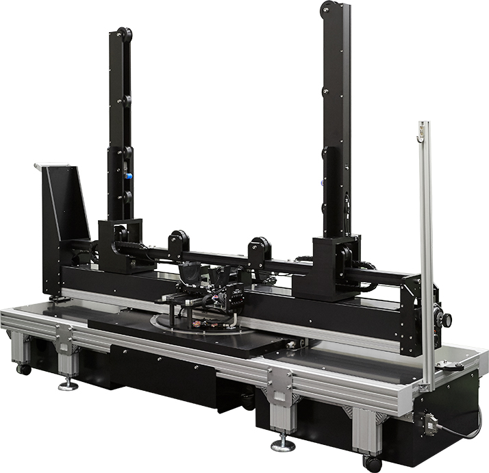
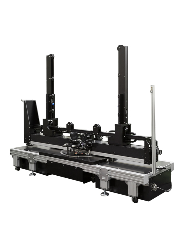
Mask Loading/Unloading System( MCS )
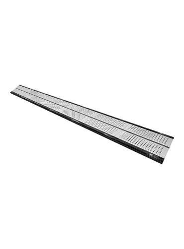
Path
Mask Rotating Device( MRD )
Photomask Transport
The mask loader/unloader system is used to remove the photomask from the case and load it into the equipment. The assist arm is used to remove the mask. The photomask can also be stored in the case. The assist arm can be used for loading and unloading for a variety of production equipment in addition to the mask loader/unloader system.
Operation is simple. First, the assist arm handle is used to set the arm in the mask loader/unloader system positioning unit and catcher. The operator then conducts operation following the instruction displayed on the assist arm monitor.
Assist Arm Movement
Remove the assist arm from the production equipment or mask loader/unloader system and then move the stored photomask to the next transport destination.
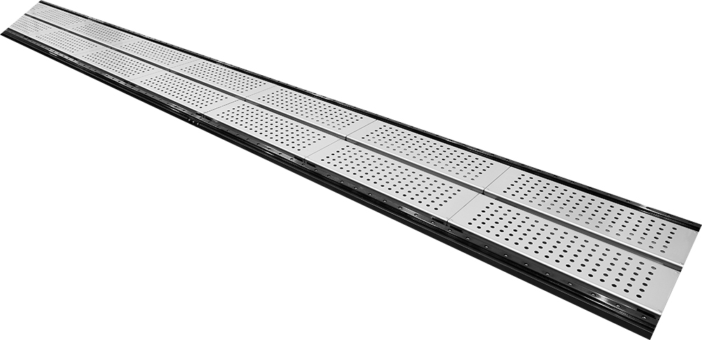
The assist arm can be easily transported by one person along the highly accurately set path.
Product Specifications
PRODUCTS INFORMATION
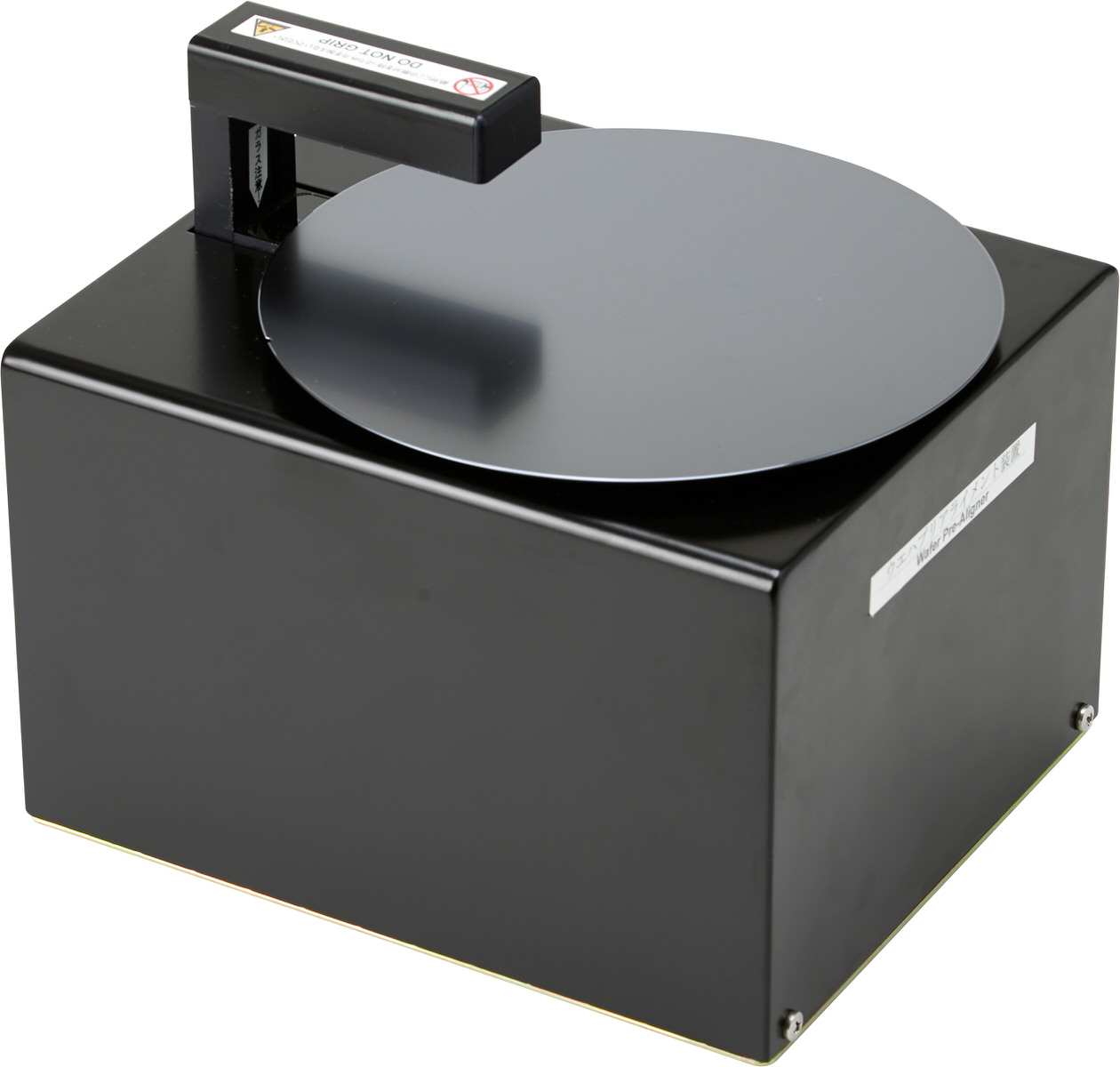
Pre-Alignment Unit ( WA Series )

TEMPERATURE CONTROL
TRANSPORT SYSTEM
TECHNOLOGY
CONTACT
We provide customization and can change specifications and technical applications to meet customer requests. Please consult with us.
Contact Form


